
With devices and gadgets becoming smaller than ever, the need for flexible PCBs is growing faster than many companies can handle. Good thing there are service bureaus, such as an OrCAD service bureau, of advanced flex and rigid-flex design that provide both design and manufacturing solutions for companies that can’t afford in-house PCB design services.
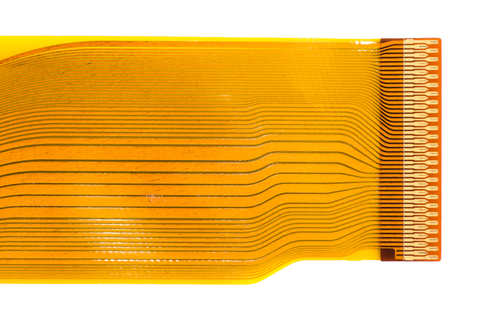
Rigid-Flex Design
This is how designers meet competitive pressures and continuing demand for more cost-effective, lighter, and smaller products. It uses flexible PCB materials to meet the form-factor requirements and their challenges, improve performance, and eliminate connectors.
What are the Challenges of Designing Flexible PCBs?
- Ensure the soldered joints don’t break when PCBs are bent
- Ensure flexible circuits have filleted pads and radiused corners
- Lack of flexible PCB design software
Fortunately, there are solutions available for all 3 challenges, including software that will make designing with flex/rigid-flex a success at first pass. Find them with an OrCAD service bureau.
OrCAD 17.2-2016
What Is OrCAD 17.2-2016?
This is a newer version of OrCAD where the cross-section editor has been redesigned to accommodate new rigid-flex features that come with different stack-ups for different technologies. From the usual OrCAD design process, new capabilities have been added to allow designers to meet flex/rigid-flex requirements and overcome associated challenges.
Features of OrCAD 17.2-2016
- Redesigned OrCAD Cross-Section Editor
- Create, edit, and manage physical zones.
- Define complete stack-up that includes conductor and non-conductor layers.
- Assign any stack-up to any zone, including parts of the flex that are unbending but where vias are allowed.
- Move a part from the rigid area to the flex area.
- Automatic transitioning of components through OrCAD dynamic zone-aware placement to the internal database layer.
New Inter-Layer Checks Spreadsheet
Typically, when designing rigid-flex PCBs, various bend areas, masks, and stiffeners need to be created, all of which require overlaps of materials, spacing and special clearances. This makes it a challenge to identify and check if all rigid-flex design requirements are met.
But the new spreadsheet provides an actual view of all the components used and of what exactly is being built. This gives designers a good idea of the changes and improvements that need to be made and to perform more accurate DRC checks.
The same spreadsheet can be used to provide better data that CAD CAM tools need for better fabrication and to receive better, more accurate feedback.
Arc-Aware Routing
To match the unique capabilities of rigid-flex designs, complex routing paths are necessary. This throws in more challenges that many designers would rather avoid. But with the OrCAD 17.2-2016’s arc-aware routing, complex routing paths are simplified.
Designers can use this feature to route a bus while complex board outline is developed and to push and shove traces to ensure that any changing requirements match.
Supports designs using IPC-2581
IPC-2581 is a design data exchange format that is open, intelligent, and neutral. It is used to exchange stack-up data electronically and communicate build intent confidently.
With the revised version, challenges in transferring design data to fabrication are resolved. Since it now supports a bi-directional exchange of stack-up data, any problems in the design hand-off cycle will be discovered before it’s too late.
In addition, OrCAD 17.2-2016 provides easy access to an OrCAD service bureau, like CA Design, providing you with complete PCB design services and manufacturing solutions even when you can’t invest on in-house PCB.
CA Design Offers Allegro and OrCAD PCB Services nationwide as well as to the Following Cities and Counties: Cadwell, Cotati, Fredericks, Kenwood, Liberty, Orchard, Penngrove, Petaluma, Roblar, Rohnert Park, Roseland, San Francisco, Sebastopol, and Silicon Valley